I personally really want an unstayed rig and have the boat as bare as possible. The reasons for this are : really easy to rig, really quick to unload and rig, inexpensive and cheap.
Four very important reasons for a boat like this. I really really want it to be such that I can unload it from my roof rack and rig it for sailing in 5 minutes flat. The only sailcraft I have where I can achieve that is with my class 5 landyacht and so I've chosen that rig for my F12 design.
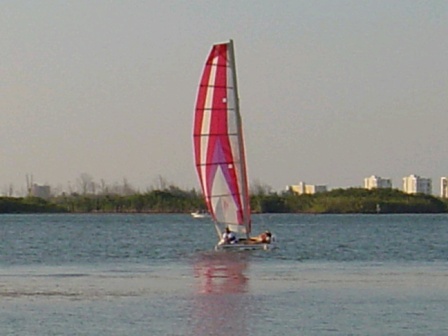
![[Linked Image]](http://www.catsailor.com/bb_files/105512-Class_5_H510_sail_big.jpg)
Of course the mast will be raked moder forward and the boom will angle up less, plus a true squaretop will be fitted. The sail area in the picture is 5.5 sq. mtr with aspect ratio 4.5. For the F12 I'm looking for a 7.00 sq.mtr. (same as laser-1) with aspect ratio 4.3. This means the mast will be slightly taller going from 5.500 mtr to 6.000 mtr. If possible then I would like to sqeeze in 7.50 sq. mtr. with aspect ratio 4.0 using the same boom and mast, but we'll just have to see if that is possible.
Using the measurements I took of different kinds of landyachts I feel that I have a good starting point for the F12 mast.
This mast will be made of standard round aluminium tubes of a high yield stress variety. The diameter will reduce in three steps when going from bottom to top and the mast can be broken down in those pieces for transport. Here the bottom mast section will be about 3000-3500 mm long and the other two pieces will fit inside the sailbag together with the sail and boom. It appears right now that the same section as used for the bottom mast section can be used for the beams. And I really want that to cut down on cost. Interestingly enough the two top peices of the mast can be inverted and slid back into the bottom section leaving a mast stub of about 3400-3900 mm length. The final lengths dependent on the flexing curve required by the sleeved mainsail. This mainsail will of course be fully battened. I will try to make some pics of my class 5 mast design which will be a slightly smaller version of what I want to do with the F12 mast.
For the same reasons of simplicity, quickness of unloading/rigging and low costs I really want to make the boad boardless and if possible (enough performance) even skegless.
The arrow hullshape is pretty much a trapezium shaped box with a curve keel panel. The vertical sides and the loaded up rudders will resist sideways slip while the rocker will still allow good tacking. This is basically the most simple multichine construction method and allows the hull to be made from flat panels that are bend in one direction only. Thus is suitable to (untortured) ply or glassed foam. In the Australia yardstick handicap system the 14 ft arrow is rated faster then the Hobie 14 and that suggests that this simple hull construction is not too much of a performance burden.
Personally I think the Arrow hull shape still looks well for such a simple construction method.
![[Linked Image]](http://www.catsailor.com/bb_files/105512-arrow2_medium.jpg)
The boat needs to be as light as possible, especially to make it REALLY car toppable and to give it some good performance as the size of the rig design is limited for various reasons. Ready-to-sail 60 kg or less.
The only way to achieve this is to build the hull as light as possible. Afterall these will make up 50 % of the total weight and are the larger single component in weight, the second largest is the mast and here we can't win much without losing stiffness or strength.
I've found a way to support the mast and rig that produces by far the lowest loads on the platform and thus allows the hulls to be made light. I really wanted something else at first but the advantages of what is shown in the picture are simply far too attractive.
First a picture of the landyacht test team that evaluated a few of the idea's coined for the F12 on landyachts.
![[Linked Image]](http://www.catsailor.com/bb_files/105512-Stighter_landyacht_test_team.jpg)
But more interesting is the way the landyacht in the background is holding up the unstayed rig
![[Linked Image]](http://www.catsailor.com/bb_files/105512-Formula_12_mast_support_concept.jpg)
As you can see two compression rods hold the mast up, there is nothing else that keeps the mast vertical under the wind and sheet pressure. The rods are hollow thin walled tubes of a very modest diameter. Also note that the line traveller system I have planned for the F12 is on this landyacht, blue line at the back, the red line is the sheet. That setup works well enough to for F12 usage. The rig and boom will be different in my planned F12 of course.
The beauty of the compression tubes is the very low mast step load that results from it. Look at how weak the tubes at the basis of the landyacht look. These hardly flex at all when the sheet is pulled tight, but when you stand on them they flex alot. This very trick I want to use on the F12 to make the required mainbeam small and light.
The way I want to implement it on the F12 is like this :
![[Linked Image]](http://www.catsailor.com/bb_files/105512-Formula_12_back_rods.gif)
The compression rods will only come back 800 mm from the mainbeam and connect to the inner side of each hull. Now I sailed this landyacht hard and I layed the F12 layout in my home and surprisingly enough these rods are not in the way of the crew. They appear to be but it is very easy to throw a leg over them or stick it under them. Also the angle inwards quite rapidly. The nuisance is less then the one associated to the sidestay on our cats. Mostly because this rod is on the inside of the hulls and not on the outside and because it lays so close to the horinzontal plane. But there are big advantages of this setup :
First, the bows of the F12 are not loaded up in anyway except resisting sideways drift, this will allow the bow sections to be build much lighter. And we can use pure foam bulkhead in the bows. Light, easy and cheap.
Secondly the reinforcing frame at the rod attachment point on the hulls will be about halveway between the two beams. A frame is needed here anyway to support the deck between the boats with the crew on it. Now we can use one frame for both uses. Also this part of the hull is the strongest and the flexing is reduced alot because it is between the two beams. The rods themselfs will put the hulls under tension and not compression which is good as well. The sideways components of the compressions rods that is pushing the hulls apart will easily be offset by the pre tension of the trampoline in this part. That is very attractive as well. In effect the trampoline acts as a "bow foil" in this situation.
Thirdly, the reinforced connection point of the rods can now be used as a third support point for the wire trampoline making it alot more firm then is normally possible. A wire trampoline setup is both simple and cheap. And it is easy to make by a homebuilder.
Fourthly, with the push rods there is no mast step load that is directed downwards onto the mainbeam ! In fact the mast step load is UPWARDS and it is much reduced. The difference is 400 kg downforce with normal stays (or tension rods going forward) to 90 kg upforce. This will allow the mainbeam to be designed much smaller and lighter. And in fact will allow the mainbeam to made out of the same section as the lower mast section. Of course no dolphinstriker setup is needed anymore and that is attractive all around not in the least when sliding the platform onto your roof of your car.
The car rack can now be made of only two plancks on which the beam slide along and rest.
And to make things even more attractive, there will be a forward directed component of the mast step load on the mainbeam but this will also be offset by the pretension of the (sleeved) trampoline. Again serious reducing the stresses in the mean beam. In effect the mainbeam now only needs to be designed to give the platform ample stiffness. And is also way that landyacht can use such thinwalled tubes of small diameters. Something we also want for the F12.
The design is worked out further then that (details) but this is the general layout and with the landyachts is these concepts have now been proven to work.
And someone has been found to make a nice CAD drawing of it so we can all inspect it to see how it looks and feels.
With this design I think I can get the boat down to 60 kg ready to sail for less then 4000 US$ with the performance of a Hobie 14.
For now it is a hiking boat only but the design not in principle prevent adding a trapeze, although some careful implementation still needs to be thought out. The beam, mast and platform should in principle allow it, but for now I only concentrate on designing a hiking boat.
Suggestions are welcomed ! <img src="http://www.catsailor.com/forums/images/graemlins/grin.gif" alt="" />
Wouter